How to Set Up Steel Bracing Systems in CAD: An All-Inclusive Tutorial
The importance of steel bracing systems does not need to be overstated in the context of the structural robustness of a building, bridge, or even a complex construction. They provide the much-needed counteraction to lateral forces harmonized with wind, earthquakes, or any other external forces. They also provide proper stability to the building or bridge. Steel bracing systems need to be laid out meticulously to ensure safety and accuracy. Designers and engineers have tools such as Computer-Aided Design (CAD) to help develop these accurate layouts.
In this tutorial, we will discuss and focus on best practices to ensure accurate and precise details are incorporated in the CAD steel bracing systems design.
Why CAD for Steel Bracing Layouts?
CAD offered via AutoCAD, Revit, and SolidWorks has notable advantages that help with bracing layouts.
Precision: Bracing systems are complex in nature. CAD tools provide intricate details that will help ensure the design is precise.
Efficiency: Time saving is CAD’s trademark feature. Creating, changing, and reviewing designs are usually modified much quicker with CAD.
Visualization: CAD provides a unique way to look at complex designs and systems from different angles, ensuring each and every component is accounted for.
Collaboration: CAD models can be disseminated to the team, subcontractors, or clients to receive input and further modifications, guaranteeing that the extracted models fulfill all objectives.
Step-by-Step on Setting Up the Steel Bracing Systems in CAD
1. Know the Design Goals
Having the project requirements in mind is crucial before launching the CAD software. The holistic building layout, the types of bracing systems (cross, knee braced, and diagonal), and the forces the structure will be subjected to are all considerations that will have an effect on the steel bracing design.
Design systems are primarily focused on lateral resistance. The layout will be determined by:
Load Path: Optimizing the transfer of forces to the bracing and from the bracing to the foundation.
Structural Elements: The columns, beams, and floors the bracing system will connect to.
Local Regulations: Bracing systems must follow local building regulations and safety standards.
2. Draw the Floor Plan in CAD.
As previously discussed, the building or structure’s floor plan, which is to have the bracing system, includes the following. Start with uploading the floor plan or drawing a new one.
Columns: Show the structural columns position marks.
Beams: Indicate on the structural plan the position of the beams that will be in contact with the bracing system.
Foundation notes: Any specific notes regarding the bracing system’s base may be added in the footer as well.
Be certain that the proper scale is used for the floor plan, as elevation detail’s accuracy is equally important. Utilizing layers in CAD to separate different structural components of the design will improve overall management of the model.
3. Choose the Type of Bracing to Use
Steel bracing systems come in various types, each for different uses in various scenarios. A few of the most common types are as follows:
Cross-Bracing: This is commonly used for buildings with large open floor plans. It is characterized by two diagonal braces that cross each other, forming an ‘X.’.
Diagonal Bracing: This is characterized by a single diagonal brace that ties a beam to a column, usually found in high-rise buildings.
K-Bracing: A K shape is formed with two diagonal braces in a single structural element, which helps the system be spatially economical.
Chevron Bracing: A single diagonal brace that connects with a perpendicular beam at mid-level, forming a ‘V,’ is typical in industrial buildings.
Selecting a bracing system will rely on the structure’s needs, design, and the space available. Once decided, draft the bracing system in CAD, ensuring the angles and connections are accurate.
4. Model the Steel Sections
Moving onto the CAD software, begin to model the steel components, which include the braces, beams, and columns. Do the following steps for each steel part.
Set the appropriate dimensions: Confirm the steel components are the right dimensions, particularly the braces’ thickness and length. CAD will ensure these proportions are accurate.
Select materials: If the application supports it, specify the appropriate material properties for each steel part, like the steel grade, yield strength, and modulus of elasticity.
Assign properties: Advanced CAD applications enable users to assign material properties to each steel part for finite element analysis (FEA), which predicts the structure’s response to stress and load.
5. Oversee the Connections and Supports
The bracing system connections with other structural components such as the columns, beams, or foundations require careful precision. CAD provides tools for these connections, which need to be modeled accurately. Some examples of these connections are:
Welds: These are modeled where the braces intersect with the columns or beams.
Bolted Connections: As with other construction seams, accuracy in bolt size and spacing should not be overlooked if bolted connections are to be employed.
Pinned Supports: While ensuring that the ends of the braces are free to rotate both rotationally and translationally, make sure that the connections are unrestricted.
While supporting structures, welds, bolts, and other connecting features, it is crucial that proper tools are utilized in CAD, ensuring that design details and building regulations are aligned with the intended connections.
6. Evaluate Load Distribution and Load Analysis
It is essential to conduct load distribution analysis after the basic braces are set. Most modern CAD systems support the integration of structural analysis software plugins such as SAP2000 or STAAD Pro. These tools facilitate the input of load conditions and evaluate the performance of the bracing system under load.
The analysis will reveal:
Weak Points: Any components in the bracing system are likely to buckle or fail due to loads applied.
Displacement: The predicted structural deflection under specified load conditions.
Stress Concentrations: Regions in the structural members, notably the steel components, that will incur damaging loads.
Adjust the design and dimensions of the steel members based on the results of the analysis.
7. Drawings and Documentation
Once your layout and the analysis are done, your next step is creating drawings and documents needed for construction. CAD software makes it even easier as it generates:
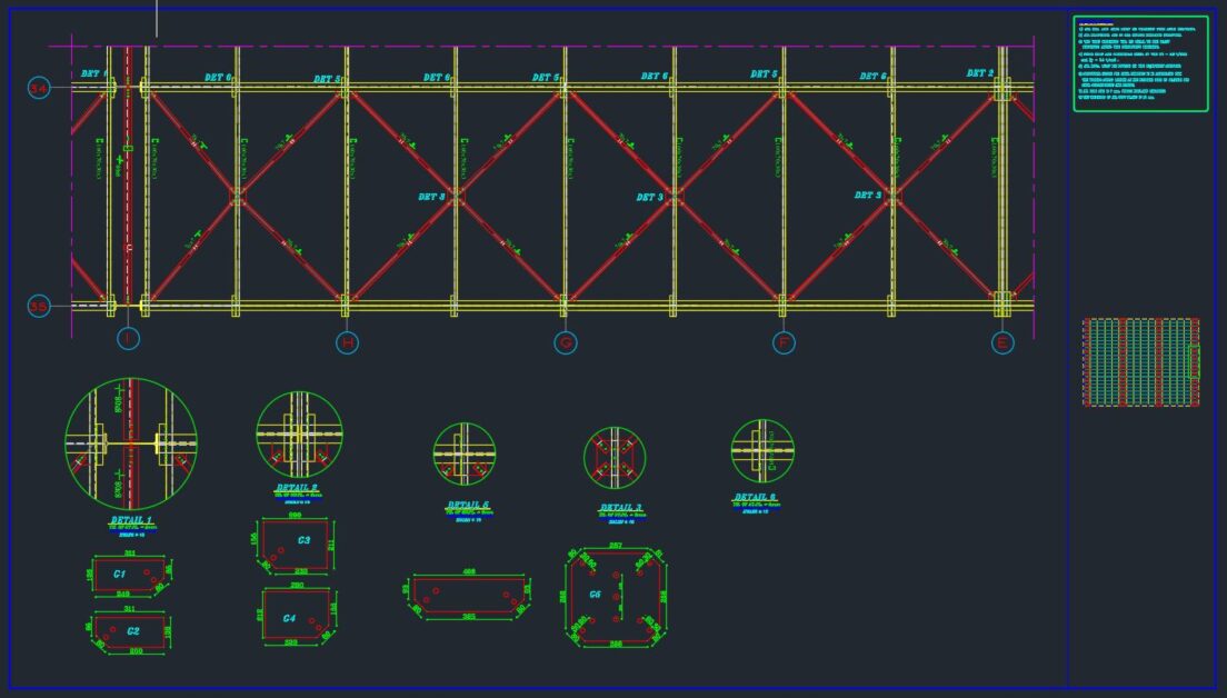
Bracing Details: Diagrams showing the intricate placements of bracing, connections, and other structural elements.
.
Assembly Drawings: Diagrams illustrating the fabrication and assembly processes for each individual component.
Material Lists: Documents that outline each material, which also include its dimension, quantity, and specifications.
Add as much detail as possible, including descriptions for bolting, welding, fabrication tolerances, and construction step sequences.
8. Cross-Check and Work Together
Before the layout is finalized, you must perform your final review of the design and CAD and share it with your team and other stakeholders for comments. Final collaboration is important and is aimed at articulation of what may have been missed.
In CAD, it is really easy to adjust and collaborate, as there will be no limitations to make it so that all issues are solved before moving to the construction stage.
Summary
Designing a steel bracing system in CAD is a step-by-step approach to careful preparation, precision in 3D modeling, and deep evaluation. By adhering to the steps listed above, your design will meet the structural and detailing requirements for the safety and stability of the structure. Modern CAD programs have become indispensable in structural design because they allow for visualization, simulation, and iterative improvement of design concepts.
Remember these guidelines in your next assignment, and the layout of a steel bracing system will be free of flaws. Any design will meet the parameters for safety, performance, and aesthetics, provided the right information, appropriate equipment, and proper methodology are applied.